Characteristics of a Sinusoidal Ac Waveform
RMS Value of sinusoidal AC current is. Generating a frequency-agile analog output sinusoidal waveform at up to 14 GHz.

The Basic Quantities Of Ac Waveform Eeweb
It is a 2 stage RC coupled amplifier that operates in two modes.
. Determine the time period T of waveform. Half-wave rectification can be achieved with a single diode in a single phase supply as shown in figure 6. For our example we will put T 2π and fx I m Sinωt in the formula.
The DC-link quantity is then impressed by an energy storage element that is common to both stages which is a capacitor C for the voltage DC-link or an inductor L for the current DC-link. Electrical Power in an AC Circuit. Calculate the resonant frequency the quality factor and the bandwidth of the circuit the circuit current at resonance and current magnification.
But what would happen to the characteristics of the circuit if a supply voltage of fixed amplitude but of different frequencies was applied to the circuit. The RMS voltage of a sinusoidal waveform can be obtained by multiplying peak to peak voltage with 122. A parallel resonance network consisting of a resistor of 60Ω a capacitor of 120uF and an inductor of 200mH is connected across a sinusoidal supply voltage which has a constant output of 100 volts at all frequencies.
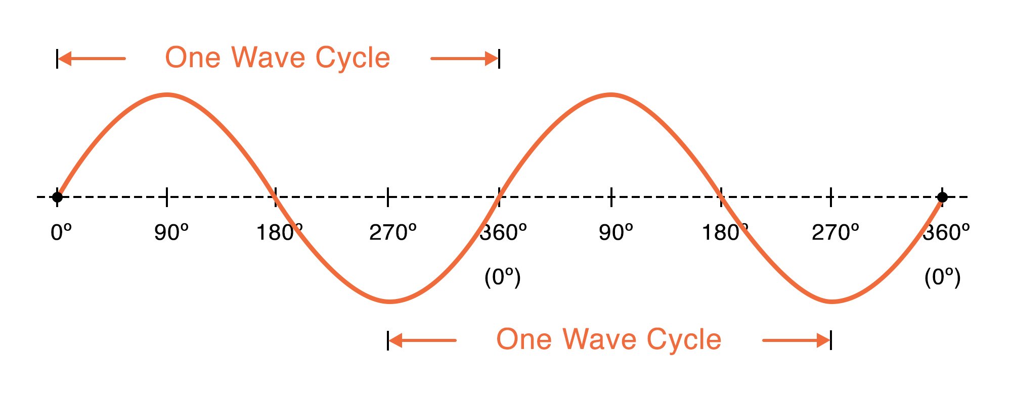
Representing phase in degrees treats one cycle of the waveform as a circle. Cation of the AC line. The frequency tuning and control words are.
It occurs often in mathematics as well as in physics engineering signal processing and many other fields. Active Real or True Power is measured in watts W and is the power drawn by the electrical resistance of a system doing useful work. For example a waveform that begins at zero displacement and shows its initial movement upward has a phase of 0o a waveform that begins at maximum positive displacement and shows its initial movement downward has a phase of 90o and so on.
In contrast the instantaneous values of the current voltage and resulted power in an AC circuit are continually changing by the supply. The custom file should be a raw text file and. Negative pulses is adjust-ed to control the output frequency.
The RMS voltage of a periodic waveform or alternating waveform is given as Vrms Vavg x π 22 Vavg 11107. For a single-event experiment with irregular timing for the stimulations a custom file can be used. The power factor of an AC electric power system is defined as the ratio active true or real power to apparent power where.
The phase difference between two sinusoidal waveforms of the same frequency and without a dc component can be easily represented as illustrated in the diagram. An average-responding meter uses averaging mathematical formulas to accurately measure pure sinusoidal waves. The AD9914 enables fast frequency hopping and fine tuning resolution 64 bit capable using programmable modulus mode.
Vrms Vp-px 1 22 Vp-px 0353. As can be seen the Phase Angle can be thought of as a percentage of the wave period measure of the temporal delay between two periodic signals. The inverter then changes the fixed voltage DC power to AC output power with adjustable voltage and frequency.
It is a type of continuous wave and also a smooth periodic function. Many ACDC and DCDC power supplies from very low power levels to as much as 150 W or more use the flyback converter. When designed and implemented well the transformer can deliver the required performance cost-effectively.
This fraction is usually stated in angle units with a full cycle. More technically it determines the effective or dc heating value of any ac wave shape. The output waveform consists of a series of rectangular pulses with a fixed height and adjustable width.
An AC-AC converter with approximately sinusoidal input currents and bidirectional power flow can be realized by coupling a pulse-width modulation PWM rectifier and a PWM inverter to the DC-link. That is one cycle equals 360o. The generated non-sinusoidal waveforms are basically a square wave rectangular wave a triangular wave sawtooth wave or ramp wave etc.
The modes are basically. Though its formula can be challenging to grasp RMS essentially calculates the equivalent direct current dc value of an ac waveform. In DC circuits the voltages and currents are constant and do not vary with time as there is no sinusoidal waveform function related to the supply.
In half wave rectification either the positive or negative half of the AC wave is passed while the other half is blocked. Often maligned and not always fully understood the transformer is the heart of the flyback power supply and probably the most important component. An electronic device that produces a non-sinusoidal waveform as its output is known as a Multivibrator.
Because only one half of the input waveform reaches the output it is only 50 efficient if used for power transfer. The overall pattern of positive vs. The time period T of the waveform is 2π as evident from its waveform.
Apparent Power is measured in volt-amperes VA and is the voltage on an AC system multiplied by all the current that flows in it. For sinusoidal modelling choose the Sinusoid option and select the number of Harmonics or overtones that you want to add to the fundamental frequency. Therefore we are not.
The AD9914 also offers fast phase and amplitude hopping capability. A sine wave sinusoidal wave or just sinusoid is a mathematical curve defined in terms of the sine trigonometric function of which it is the graph. With Custom 1 entry per volume you specify a single value for each timepoint.
We have also seen in our tutorial about series RLC circuits that two or more sinusoidal signals can be combined using phasors providing that they have the same frequency supply.

The Sine Wave Explained Ac Waveform Analysis Youtube

Ac Waveform And Ac Circuit Theory Of Sinusoids
Characteristics Of Sinusoidal Signals Sine Waves Video Tutorial

Ac Waveform And Ac Circuit Theory Of Sinusoids
No comments for "Characteristics of a Sinusoidal Ac Waveform"
Post a Comment